The actual exhibits have now been published on the JAR2 website here, or on Cryptome here, and so interested scientists and engineers can check for themselves just how dishonest the prosecution were being when they tried to use this material to convict me. Dr Eamonn Maher’s report can be found here or here.
Before I had the chance to read Dr Maher’s report I was asked by my solicitor Richard Jefferies to give my explanations about what these pages contained. Below are the notes that were produced from my evidence, which I had to produce totally from memory as I had no access to any other technical material about the exhibits.
Comments on rugate filters for SDI
Page Reference: 176-178, Exhibit Reference: JS/16
This document is one of a series of five documents exhibited by the Prosecution written by me at different times. I used block capitals on this and the other documents because my handwriting is bad and I wanted these documents to be readable by me or other colleagues at work. The general provenance of this document is from work I carried out as an Auditor of this Group’s work. The audit was carried out on this particular division of four people which is a sub-division of the photo-optics department at GEC. This particular division is headed by Nouri Nourshargh, his principal colleague is Adrian Greenham and there are two others whose names escape me who are working on the project - by the project I mean specifically Rugate Filters. I will explain further in this statement exactly what these entail at an appropriate point.
I carried out the audit with a colleague of mine called Bill Tatham in or around the beginning of June 1992. The audit lasted for about an hour to an hour and a half. My role was to investigate the quality assurance aspect of the work which involved discussing the project in some detail. I discussed the project exclusively with Adrian Greenham in his office although he did show us round the laboratory briefly. Bill Tatham was present at our discussions throughout.
It is standard practice at GEC that when an audit is carried out two Quality Assurance Members would go to the appropriate department and would ask questions of the person being audited.
It should be possible to pinpoint exactly when the audit took place because a Schedule of Audits is kept on a rota basis planning audits a year in advance. This would specify the month and area in which the previous audit had taken place - audits generally speaking would take place on an annual basis. Indeed this information is contained on one of the disks in my computer at work.
The precise time and date of the audit would be either in my work diary or possibly also on my computer. I was responsible for programming the audits in advance, a task of organisation which I have undertaken since May of 1987.
When an audit would take place both auditors would take with them a rough checklist of matters to be covered. In addition to the rough checklist both auditors would make notes of matters which they would wish to raise with the person being audited and notes would be kept of that person’s response during the course of the meeting by both officers on a standard A4 notepad. The pro forma questionnaire was merely a guide to auditors and not absolute. Throughout my employment with GEC I have kept my own separate notes. This is something that I picked up from my former manager, a man called Trevor Elson who was keen to build up a personal library of matters which had been raised with a particular department over a number of years.
Once the audit had been carried out deficiency reports would be raised. This would be signed by the person who was being audited and in this particular case it would have been Mr Greenham. These reports only relate to deficiencies within the system that we have assessed i.e. it would be a matter of highlighting problems in the particular department from a procedural level. It would not be my task, for example, to identify problems with the actual matter being researched or developed. Once a report had been prepared a copy would go to the person audited, to the manager of the person who was audited (usually the area manager), to the quality manager and our own copy would be kept by each of the individual auditors. In addition, a copy would go in the quality assurance library. The report would be prepared by the person who carried out the audit, typed up and signed by the auditors. Either of the two auditors, if two auditors were used, would prepare a report although only one auditor would actually prepare the report in handwritten form which would then be copy typed by a separate typist. I believe in this particular case, Bill Tatham prepared the report because he was low on work. My only input in this particular case was to agree that there were no problems found.
The document at page 176, I would guess, was prepared within a week after the audit had taken place. I cannot say whether or not Mr Tatham’s report had been prepared at that time. I prepared the exhibit at page 176 at work. During the course of the audit I would have produced rough notes either on a pro forma questionnaire or on my notepad and would then turn these into the form shown on the exhibit adding anything I could remember of my discussions, or our discussions with Mr Greenham. My current departmental manager, Dennis Barlow, wanted us to use the checklists as permanent records but they usually ended up in a mess and therefore we were encouraged to try and keep more coherent records.
These notes in particular were prepared for the purpose of building up a useful record for further auditors, i.e. questions to be asked the following year of what had been discussed the previous year. I cannot remember when I had last been to this department and I suspect that I did not carry out the audit in 1991.
Dealing with this matter in detail - Rugate Filters arc optical filters as I understand it and they are used with laser beams/light and as the name suggests they filter light from laser beams and essentially what they amount to is protective goggles so that when someone working on a laser is carrying out repairs that person can wear these particular goggles to see the laser beam working. The division as a whole, i.e. separate from the four individuals previously named, dealt with Photo-Optics generally as well as Rugate Filters - this particular division dealt with the SDI or Star Wars aspect specifically. The Star Wars aspect wasn’t the object of this audit, it was the general work of this Group. SDI was part of our general discussions and was probably dealt with in a matter of a few minutes. I used SDI in the heading on page 176 to remind me this was the major contract at this time.
It would be perhaps the fairest analysis to state that this division dealt with Rugate Filters which happened to have an SDI use. The only other use I am aware of is coating for goggles. Essentially they amount to a protective coating which would block out a laser frequency. I have no idea of the applicability of this to SDI. I can confirm that I assumed from the discussions that we had with Adrian Greenham that if something could be done to block laser beams then this of course would have a defence application.
Dealing with the Exhibit at page 176 in detail the first sentence indicates who the customers are. In an audit, one of the first questions to be asked is who are the customers for the project. The auditors would then move on to talk around the customers and the project because in following years we would want to see progress made. The significance of the RSRE and DRA is that that signifies that the project has an MOD usage. That is important for quality assurance people because the MOD has specific requirements relating to a military standard of work. Indeed the record keeping for the MOD work is different from that of what one would term general GEC projects. The second sentence relates to the first sentence.
The third sentence relates to a future project. I have no idea who Bill Woody is. I find it useful to keep names to raise with people on subsequent occasions. The fact that he is described as a high level person indicates the level of interest in the project.
The fourth sentence simply indicates that when talking to Mr Greenham we also discussed how the project was going. Obviously if the project was going to be scrapped this would be relevant for the quality assurance department as a subject of future audits. More particularly it will be generally accepted that one of the purposes of an audit is to provide a snapshot of a particular department’s work past, present and future. Clearly planning is one of the questions asked in an audit i.e. what is expected by the Company at different stages.
This again can be confirmed because quality assurance people work to a quality assurance management system contained in the Company’s Quality Assurance Manual. This is based on an AQAP1 NATO Standard (AQAP stands for Allied Quality Assurance Procedure) and British Standard 5750 on how quality assurance systems should be organised. Both lay down in a coherent form what needs to be done to operate a company successfully.
Indeed, I can confirm this because I wrote the document on how to do audits in the Company and this is called the Audit Procedure Guide and its reference number is QAG010.
Implicit in AQAP1 and BS5750 is the concept of completeness in keeping full records including the importance of placing any separate function in a company within the aims of the Company as a whole.
The fifth sentence of this document details the general type of activity the Group was involved in. The drawing is simply an illustration of a general principle explained to us by Mr Greenham. I am not technically competent to analyse this particular drawing but it is an aide memoir as to why this division was doing something. If one understands what a particular division is doing completely then one can make a better assessment of how to approach and identify weaknesses in their procedures.
Page 177:
First Paragraph - This is a synopsis of what Adrian Greenham said in the course of his discussions with us. It indicated what had been achieved by them at that stage on the project.
The reference to 1.9 nitride shows the upper limit of the index achieved. Its purpose is as a reminder to ask whether at the next Quality Assurance Review either that a higher refractive index had been achieved or that the project was regularly achieving the figure that Greenham had mentioned.
The reference to “refractive index” again should be seen in context. A refractive index relates to the principles of a prism. A prism bends light. The refractive index is the material effect any given material/substance has to light and the ability it has to slow the light down.
Adrian Greenham was using different materials one of which was nitride. The reference would again be a reminder to me to keep under review other materials that he was using in the process (for example the reference to silicon oxynitrides on page 1).
My general comment would be that this was a simplistic overview of the project. Its only significance would be what was transpiring the next time.
Though there are references in my manufactured note to chemical formula I don’t know the significance of the gases that were being used and this would have been recorded purely for information purposes only.
A similar comment applies to the reference to chemicals. I concede that if I did not know what the gases were at the time then there would have been little use in knowing a year later when one went back for a further review. However, usually if I was interested in a project I could research the project in more detail and it may be that this is a classic example of my scattershot note taking jotting down anything that I saw that was significant at the time. It is likely for example that I saw the chemical formula and gases whilst in the laboratory as opposed to that being anything that Adrian Greenham specifically would have told me himself.
The point that I would make in general terms is that necessarily an audit is a sample/snapshot of what is occurring on a particular day.
Notch Filter - this was on display in the office area outside the laboratory. It’s simply an example of the way that the filter works.
It relates to the Fourier transforms mathematical formula. I was surprised that the principle which has applicability in electronics could also be applied to light. It is likely that I simply noted this down as a point of some significance to me. This is a well known principle familiar to anyone with any experience in the field.
The first diagram drawn indicates the blueprint/principles for the manufacture of the filter.
The second diagram drawn illustrates the wavelength of light at which the light is blocked.
Page 178:
The first sentence indicates that software programmes are written by the team to help design the filters. The diagram relates to their attempt to filter out two frequencies at the same time. The idea is to make one goggle capable of dealing with two different laser beams. The next sentence indicates that the aims of the project are to increase the filter to deal with up to 10 different laser frequencies in due course. The whole purpose of this information is to keep under review how close Greenham’s team was on subsequent audits to achieving the target indicated.
The next paragraph simply indicates some goggles are being manufactured to deal with different types of light. These goggles were being manufactured for a specific purpose. The purpose is one I have alluded to above.
The final paragraph is simply an expression of Greenham’s stated intent to cut out frequencies up and down the band of frequencies. The general point is made as to why this would be useful. I indicate in the course of this some of the applications.
The Goggles are a totally separate issue from SDI / Starwars. Obviously the same principles could be applied to blocking laser beams used within the Starwars system. However the general point is that in this note I am recording a specific function. There is no direct mention of any applicability to the Star Wars project itself. One would expect as a layman a considerable difference between the principles applied here and the Starwars system in due course.
Further comments of the defendant Michael Smith on rugate filters for SDI
Exhibit Reference JS/16, Page Reference 176-178
The raw materials, gases and vapours are heated up under pressure in a special chamber and subjected to microwave radiation (as in a microwave cooker). By carefully controlling everything, a film of the required material is deposited on a substrate to create the filter. The way the material is deposited is controlled by a computer programme which in turn depends on the type of filter required. The filters can be designed to remove light, for example, laser light at a particular wave length. One filter can be designed to remove light at several wavelengths at the same time.
The filters are more or less clear and just remove the light from a narrow band of wave lengths. This makes them ideal for goggles for people working with lasers so the goggles do not need to be made of nearly black glasses to enable people to see what they are doing whilst being protected against particular lasers they are working with.
As an illustration of this principle a two notch filter would work as follows: -

Example of a two notch rugate filter
It will be noted there are no documents relating to rugate filters in the bundle. This is because the information would be kept in an individual scientist’s notebook and I would have no reason for looking at those. The process would only formally be committed to paper if it were a fairly well defined process. This was experimental and at the stage I audited it, not worth formally documenting. This is the reason why I would prepare the notes in the way that I have done as otherwise there would be nothing else to refer to. Whilst it is true they have working examples, these need scaling up ten times.
Comments on micro-machining project
Page References: 179-181 Exhibit References: JS/17
In general terms all these reports were prepared at the same time probably over a period of a couple of days. I cannot chronologise this particular document in relation to the other four that appear.
The micro-machining project is to develop a technology whereby small devices can be manufactured for use in small mechanisms such as pumps and valves, indeed the applications that I allude to in my notes.
To the best of my knowledge, the printing, data handling, telecoms, medical and fuel injection aspects of the project referred to are all commercial aspects.
The reason for listing this information is again solely in the context of a Quality Assurance standpoint as a reminder to me to ask in due course as to how the Company was getting on within the specific applications of the technology at hand.
The information in this note came from a series of talks at HRC. The purpose of these talks which are open to everybody is to educate those not involved in a project with what was going on. The lectures to the best of my knowledge were held fortnightly. There where 3/4 to my knowledge. I attended this one and the olfactory research project one purely out of personal interest. I recall that there was possibly one on superconductivity. I didn’t attend this.
Details of the lectures would possibly have appeared on the general notice board. In due course when the meeting was due to be heard it would be announced over the public address system within the Company. There was no need to book or sign to say one wanted to attend a lecture. One simply turned up. Twenty or thirty people attended this lecture given by Dr Perrera who is in charge of this project. It was held in the lecture hall at GEC and took place in June.
The reason behind my attending is simply that I was due to conduct an audit of this particular project in due course. I completed this audit and these notes are a combination of what I learnt at the lecture and what I learnt during the course of the audit.
These notes were prepared as a record of the state of the project for quality assurance audit purposes.
The only application as far as I am aware of this technology was commercial and indeed as I understand it all the sponsors of the project were commercial ones.
Fluidic Devices - this shows the general areas and slides were produced which have more details. Fluidic Devices means to do with gases or liquids. They deal with the process of control by any device over any gas or liquid passing through the device.
The reference to beam deflections indicates that a flow of substances can be deflected for an unknown purpose.
The reference to analog (old style) relates to the technique where one puts in a certain input and one gets an output proportional to the input and hence a range of control. An example of this would be a control of 0-10 in a smooth range. It could relate to a technique of printing on paper. The reference to beam is simply because it is considered as a beam when one expresses oneself in this field.
The reference to bi-stable obviously means two states and relates to the digital reference 0 or 1. It indicates that one can switch flow from one stable state to another without loss of performance. This relates to print heads.
Micro-actuators - this relates to the small switches necessary to control something, e.g. pumps or vortex valves. The notes on this page don’t seem to relate to printing - they relate to a range of things for the future. This is the reason behind the reference to “heat transfer devices … optical devices other areas”.
The applications relate to processes made in silicon technology and miniature devices to use in the application described. The whole point of the exercise is make devices that don’t take up much room or require much power to drive them.
The reference to transducers and photo-technology indicates the technique whereby images on silicon can be made so when the silicon is etched bits that are not required can be removed. This is an applicability to micro-circuits.
Page 2 Pressure Transducer - this simply indicates that an electrical property can be controlled. It is a well known technique. The negative resist refers to the way that the lid is put on. I drew a diagram because it was on the board. I can’t explain the significance of this diagram at this stage.
Ink Jet Print - these are simply notes by way of illustration in relation to the principles referred to on page 1 of this document. The first line indicates the things they were trying to control. The significance of this is to ensure that in due course one asked questions about the right things i.e. what they were doing regarding improving or measuring performance and whether or not they were achieving consistent results.
The last line refers to the fact that because of the size of the devices there have been problems with the finish. They had discovered that nickel plate etc had given sharper definition to the device and hence greater accuracy to the dimensions.
I would ask for example on a quality assurance visit why they had done it that way and what improvements they had made and were anticipating.
The document or sentence is simply a reminder to me to ascertain the progress regarding the developments and refinements of the technique for future audit purposes.
Fluid flow module - I have done a rough diagram of the nozzle.
I have also given an illustration of what bi-stable means. It shows the fluid ink following an arrow and going one way or another. One can force the ink to change direction using the switches. The purpose of this is to maintain the flow of ink to the nozzle in a steady state.
The operative levels achieved to date in this project appear at the bottom right hand of the page and again clearly this was information relevant for audit purposes.
Spiral Fluid Diode - this is simply an example of the application of the micro-technology I have discussed prior. A diode is a one way device. The application is simply anything to do with fluids or gases. It is an illustration of the general nature of the notes that I was creating.
Cryogenic refrigeration - this is to do with pumps. If the gas goes through a small hole a refrigeration effect may be possible, i.e. the project were working on localized cooling to ensure that if the component in the circuit got hot because of overuse it could be cooled down.
Design - this is simply a schematic of the nozzle. There is no sinister application in this note generally whatsoever. No detail is given and the principles involved are well known. As stated I did an audit of this particular project in June, again with Bill Tatham. Having completed the audit, the notes would have been placed in my filing cabinet at work and hence taken home when I left Hirst GEC.
Comments of the defendant Michael Smith on the micro-machining project
Exhibit References JS/8; JS/17 and JS/44, Page References: 270; 179-181 and 276
Introduction:
Most of the funding for this work appears to have come from AB Dick, a printer company in the USA. This is because they have a commercial interest in developing an improved ink jet printer head which gives as good, if not better, results compared with current output from laser printers. The other work for pumps, valves, cryogenic refrigeration, etc were not well funded and little work has been done to fully develop those devices.
As these devices are small and will only be a few millimetres in size they are suitable for being made in the same way as micro-electronics are manufactured and for this reason the basic material used is silicon. This also means that as the technology develops additional circuitry for controlling the devices or interfacing with other equipment can also be built into the silicon used for the micro-machined device. The devices are formed by cutting trenches and holes into the silicon and then bonding a lid over the top to enclose a space or tunnel. Piezo electric switches (which move when a voltage is applied to them) are used to control the operation of many of these micro-machined devices.
[Solicitor’s comment - piezo-electrics means materials which, when put under pressure generate a voltage.]

Example of micro machined nanotechnology device
Comments on quasi -optical car radar
Page Reference: 182-185, Exhibit Reference: JS/18
As previously stated I am not sure how close I did the writing up of this particular note to others previously discussed.
The date relates to May of 1992. I believe it relates to the 14th of May which is the date that I was made redundant and I simply recall that possibly these notes were made on the morning that I was told that I was being made redundant.
I carried out an audit on the microwave group which is part of Mr Swallow’s area. We only carry out one audit on this group per year. The group that relates to the specific project was autonomous and consisted of Peter Brigginshaw, the Project Leader, and another Indian gentleman, whose name I cannot remember.
The work of this particular team of two revolves around microwaves. The range of frequencies is similar to radar. When frequencies get to a higher range they develop quasi-optical phenomena. When radio waves behave like light they can be bent with lenses and reflected.
In radar work there are advantages with dealing with these higher frequencies. I recall that the audit was carried out with Bill Tatham. We went to Peter Brigginshaw’s office and discussed the project and notes were made in the course of that. Both Bill and I made notes. Bill is an expert in this field and I believe that he would have been the more dominant of the two of us in terms of the question asking.
I carried out two previous audits on this group regarding the same type of thing but not this particular project. The project is not a recent project and doesn’t have high priority to the best of my knowledge.
I believe that this project has at some point in the past had a military application originating as military work for a government agency in Malvern. I believe that approximately five years ago they were trying to develop a radar to use on helicopters. I am not sure of the make of the radar but its general purpose was to detect the size of vehicles.
This project is therefore an application of that although I am not sure of the connection between the two.
I would state generally that the information produced in this note is not classified. As previously stated, it was derived from an audit lasting approximately an hour and a half. Again the purpose of this document is for general background. The principle of the optical car radar is to detect obstacles, obviously other cars, in for example fog. It could have military applications but as my second paragraph indicates it was only funded by commercial companies.
There is no significance that can be attached to the first line. The name is not of significance save if changes were made to the project structure. It was possible for example that Mr Brigginshaw could have moved on during the course of the project’s development.
The Omega Prometheus project relates to the radar. Other electronics relating to this, for example, the switches were being done by another company. The reference is simply a reminder to myself that this particular project was part of a much larger project. I am not sure but the project may indeed have been funded by the EEC. The whole project is to produce a reliable workable car radar system for use on roads.
If the military were involved/interested in this project I would expect a different set of standards regarding the work. The fact that it is for a car tends to demonstrate the commercial applicability only for the project. In fact I would expect a military application to result in a different project entirely. Indeed if a project did have a military application I would have expected it to have been funded by them.
The second paragraph simply indicates that the companies sponsoring the work are in competition with each other. The significance of this to me is to discuss contracts in the scope of any future audit.
Other companies are relevant again within a quality assurance framework because the performance framework they require and the possible markets for the fruits of the research are matters that would be continually assessed.
The reference to Peter Brigginshaw funding the work by outside money indicates that one would have expected him to tailor demonstrators to the requirements of any individual company.
On a separate topic, but perhaps significant to this stage, an illustration of why this would be significant is on one occasion we found in the course of an audit reference to an outside company. This was to do with a company called A B Dick and referred to Polymer LCD’s. These were applied in thick liquid form onto a plastic base and one could then photo onto this information and erase or re-write as required. AB Dick in the USA wanted Hirst GEC to develop this project.
I would guess that the purpose would have been to update, for example, an ordnance survey map. EEC bodies funded the research. The EEC project was funding the development of erasable and not updatable LCD’s. We discovered that the EEC money was being used in connection with the EEC Project and also in relation to the project that we had been asked to prepare for A B Dick and hence for A B Dick’s commercial advantage.
This in due course created a nightmare because when we were going through the audits we couldn’t identify EEC / AB Dick requirements.
Because at our level we couldn’t resolve the problem, we had to go to Dennis Barlow and then to the Assistant Director of Hirst GEC, Michael Clark, who in turn passed the complaint on to Stephen Cundy to resolve. In due course we were told to hush the whole thing up because of course the Company was effectively being paid twice for the same work.
Also, perhaps to amplify on this, where Hirst was sponsored by an outside Company one of the things as quality auditors we would be looking at is where there are overlaps between customer requirements.
Clearly, once funds are transferred between projects long term complications can arise particularly if funding is withdrawn.
I would concede that the optical research was similar to research for the helicopter referred to above. However what I would say generally is that the test equipment being used by Brigginshaw was not in accordance with military specifications.
Third paragraph - this demonstrates how one can focus the radar using a standard lens. The diagram shows how this works. Simply one transmits a beam which bounces off an object back to a receiver. The principle was that they have three different receivers for a beam to target on and therefore could search across a wider field.
Page Two - the illustration on page one is the ideal of what the project was hoping to achieve. The idea being that one lens could be used for the three directions. However I recall the fact that the project was finding a less well defined response. Hence the reference on the second page to a possible solution to the problem which is to switch between side lobes using a modified lens.
The relevance to audit management is simply to indicate it is the Client’s responsibility to ensure whatever is right.
The reference to Peter Brigginshaw simply indicates that he thought it wasn’t a good option. These notes are simply relating to background again for future audit purposes. I would be the first to concede that sometimes what I write down I don’t necessarily understand. 10° is the target one has to obtain and clarifies the aim of the project. Different directions give a wider coverage of the system. This paragraph simply confirms the usage of the project.
The next paragraph confirms specifically the aims. The next paragraph relates to the aims and timescales of the project.
The rest of the system was not being dealt with by GEC just the research and therefore one would record this in order that on an audit one could ensure that the part Peter Brigginshaw was dealing with would interface with the work the other collaborators were performing. This explains the last paragraph on the second page.
Page 3 - the diagram is simply an aide de memoir for myself. The diagram is from drawings shown to us in Peter Brigginshaw’s office and is amplified by Brigginshaw’s explanation - note the absence of any calculus / electronics of which were glossed over.
I have made the point before and the point remains that these notes are a general impression of what the object of an audit is. This is to understand and give a feel for the project in hand.
The second paragraph relates to Peter Brigginshaw telling us that the system used detectors and that he had found a better way to manufacture the detectors which he was patenting to combine transmitters and receivers. This would be company confidential information but there is not sufficient information or detail to assist anyone looking at this document.
In terms of quality assurance work, this would have been classified as an ongoing project and at this stage no working model had been produced. One would look at better or similar results on one’s next visit as previously discussed.
Page four - the diagram demonstrates how the systems worked. TX means transmitter and RX means receiver. The second paragraph indicates that it is simply one of a number of projects.
Other work that Peter Brigginshaw does has bearings on specifications and materials used and we would need to know this to ensure for example that he had the requisite calibrations on measuring equipment at the frequencies he dealt with. Questions in due course would be asked of this regarding his progress.
To the best of my knowledge there is no connection between these paragraphs and the rest of the document referred to. I assume similar principles are involved (no details known) because we had no information or whether there was a solid project in hand.
I am not sure if the principles enunciated thereafter are relevant to the rest of the document. One can see broad similarities but the design is so different that it is clearly not the same project.
In fact they would involve totally different specifications - not road but air. They have a much greater range and a far greater degree of accuracy and a much higher speed of operation giving much wider angles. Similar comments apply to the last paragraph.
Comments of the defendant Michael Smith on quasi-optical car radar
Exhibit Reference JS/18, Page Reference 182-185
The Project gets the name Quasi-Optical due to the phenomena that when the radar frequency gets up to 50-100 Ghz then the radio waves start to act in a similar way to light (because the frequencies are approaching that of light). The radio waves can then be reflected from surfaces like a mirror and refracted and focussed like using a lens on light beams. HRC does this quasi-optical part of the work dealing with the equipment that will transmit the radar beam from the Gunn diode transmitter and receives the reflected signal and decode it in a mixer.
As noted on page 184 some aspects of this have been, or are being, patented and will therefore be in the public domain. The comment on page 185 about “missiles with Lear in the USA” and “poisonous gas clouds” were only at discussion stage and were not discussed at the audit. By this I mean that during the audit with Brigginshaw we touched on other contracts that may have come to fruition. We did not go into detail about these contracts and I simply put down the two that I remembered.
Beam swinging scanning systems are not new. A lecturer of mine at University - Edward Watson - told us in 1967/1968 about such a system used on missiles that he had worked on at EMI in the 1950’s. The car radar system was being developed for civilian use and the specifications of the system would be with this in mind. Peter Brigginshaw did do work on military systems but this would have been a completely different project.
Comments on micron-valve project
Page Reference: 186 Exhibit Reference: JS/19
The project is for producing small cones which, when connected to a voltage source give off a string of electrons from the tip. The application is for valves for example cathode ray tubes and fusing systems. The project is trying to develop a technology to produce devices and has five sponsors.
The idea is to increase the current carrying capacity of any given device. Normally to generate the electrons one has to heat an electrode and the point of this project is to try and achieve a principle whereby it can be done without heat. The advantage would be a reduction in power to generate electrons together with the fact that when things are heated up they can become unreliable and in certain circumstances heat can be detrimental to the application/apparatus.
A company in France are doing similar work. The devices as I understand the position are to be used to develop a flat television screen.
The information in this document came from an audit carried out by myself and Tony Youles. The audit was carried out in May of 1992. I cannot be sure when this document was written up.
The audit was carried out on an associate of Neil Cade whose name I cannot recall. Cade is head of the Micron-Valve Division in the new technologies laboratory.
The division consists of four/five people. The audit was confined to the office itself and did not involve a visit to the laboratory. I know of no military application. However I believe Marconi Defence may have been funding the project but only in terms of that Company’s desire for diversification. The audit lasted for one hour.
The document herewith was to give background for others on the quality assurance side.
The information contained in this document is company commercial.
I wrote the quality assurance progress report.
First two paragraphs - these are a statement of the projected aims of the project. The leader expressed concern over unexpected results. The team had been trying to understand what makes a good “tip”. He mentioned the machine to find out the make up of tips. The impression that I had from the documents he showed us was that there were doubts as to why some tips were good and some tips were bad.
The second section of this page indicates the process whereby tips would be manufactured in blocks on a piece of silicon and mounted onto a carrier for testing purposes. The team had encountered problems with mounting and I indicate that two methods had been tried. This directly relates to quality assurance work.
The next paragraph cross refers to another audit and again I illustrate for future reference the principles involved.
I conclude with an assessment of the capacity achieved at the time of the audit.
Comments of the defendant Michael Smith on the micron-valve project
Exhibit references JS/8; JS/19 and JS/44 Page References Page 270; 186 and 276
Introduction
This project is important because it is based on something called “current density”. Take an example of current flowing down a wire:
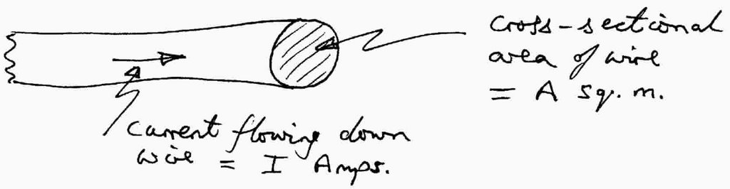
Example of current density
Current density will be = I/A Amps per square metre
There is a phenomenon in physics, that when drawing electrical current from a tapered point the current density is magnified and it is this aspect that the micron-valve project is investigating. Two types of device have been produced: -
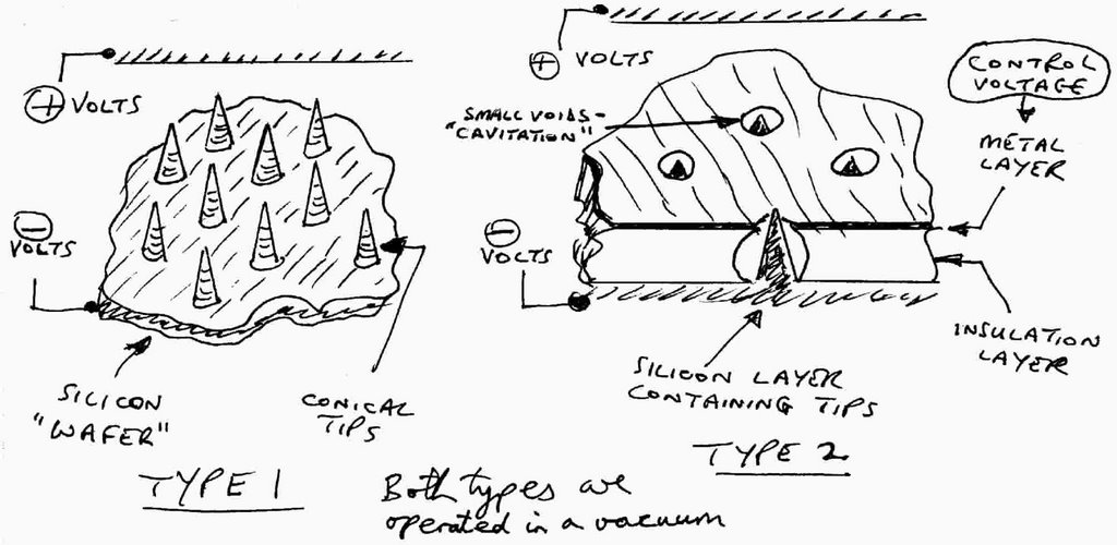
Two types of micron valve device
Type one
Most of the work so far has been done on producing hundreds of these little cones on a slice (or wafer) of silicon. Each of these cones is only a few microns (millionths of a metre) tall. When voltage is applied to the cones (this is called the “cathode”) and a voltage is applied to a plate above (the “anode”), current is drawn from each tip as a flow of electrons. If too much current is drawn then the tip will overheat and burn out.
The two applications that I am aware of are firstly as a cold cathode for a cathode ray tube (which normally requires a heater to generate electrons) and a fusing circuit when the current exceeds the maximum tip current - this will protect some other circuitry.
Type two
This is where the project gets its name - micron-valve. When voltage is applied across the device, by adjusting the voltage on the metal layer it is possible to control the amount of current flow, so making this a valve.
I have done two or three audits in this area between 1989 and 1992. Neil Cade is the Project Manager and he decides what will be the requirements for the next batch of processed wafers. Wafers are processed in the Silicon Clean Rooms. The wafers are returned to the micron-valve staff, who cut them into pieces and mount them on “carriers”. These carriers are put into a vacuum chamber in the test area (room F19) and the characteristics are measured.
There have been lots of technical problems, lack of funding and poor co-ordination between different groups of people and Neil Cade said in 1992 that they still didn’t understand how to make reliable devices/tips from this process.
NB Audits that I have been involved in will be listed in my audit schedule, which the police have a copy of (item MN/13)
Comments on olfactory research project
Page Reference: 187, Exhibit Reference: JS/20
This is the mechanical means of detecting gases and in layman’s terms an “artificial nose”. This enables the detection of very small constituents of what constitutes a smell and also has applicability in the field of humidity measurement.
This could have a military application but the funding was by a Swiss company whose purposes were to control smell mechanically rather than by the use of people’s noses. My understanding of the position is that this would have use in perfume/wine manufacturing.
The information contained in this note came from a lecture given in the GEC Hall and was part of the series referred to before. I attended this lecture as it was an area that I had audited previously. It was due for a further audit and I wanted to keep up with what was happening in the field.
The lecture lasted for approximately half an hour and the purpose of these notes was simply to update my own knowledge. The lecture was an extremely technical discussion of the operation of the devices produced. As I understood it, three people were working on the project. It effectively was the canary in the cage syndrome.
In general terms the idea was that the chemicals would be applied to films to determine the vapour that needed detection. The document is expressed in general terms and contained company confidential information.
The project has reached the stage where working devices have been produced which shows that the principle is reproducible and works, but I don’t believe that the project has yet reached the commercial development stage.
First Paragraph/Diagram - the pattern recognition methods is to do with output from this device when connected to an external circuit. It produces a unique response pattern directly proportional to the sample and the easiest analogy to give would be that of a fingerprint.
A SAW is a Surface Acoustic Wave Detector.
The diagram shows in a crude way how the device is made up and effectively it is part of a much larger circuit.
This indicates that the things are made consistently to the same standard. The quartz plate has a SAW etched onto it. Both sides are coated with film sensitive to the gas. In this paragraph I give an explanation as to how the thing is made.
The next paragraph demonstrates that when a sample gas is passed over the device two phenomena take place: -
i. at the surface between the gas and film reaction the gas is slowly absorbed into the surface and changes in density and therefore the device needs time to recover; and
ii. the gas is absorbed to the device.
One would need to know this for quality assurance purposes, i.e. how many times the device was used and whether it is reproducible or reusable.
Next Paragraph - the first sentence is self explanatory and relates back to the last paragraph. It gives details of the work on bulk acoustic wave devices. These are the solid lumps of quartz and less sensitive than SAW’s.
I am simply illustrating in this part the sensitivity of the items.
The advantage of bulk acoustic wave devices is that they are cheaper and that they can be used for humidity consideration.
Comments of the defendant Michael Smith on olfactory research project
Exhibit Reference: JS/20, Page Reference: 187
The principles behind this project are to try to detect a gas/vapour in a similar way to the method the human nose uses to detect smells. Gases/vapours are made up of a unique mixture of molecules that the nose detects and identifies by a combination of the effects on:-
(a) the sensitive membranes in the nose;
(b) the messages that are sent to the brain; and
(c) the decoding of messages in the brain that lead to recognition.
It is unlikely that an artificial sensor would be as versatile as the human nose but would probably be designed to detect particular gases or vapours. A sensitive coating is applied to a Surface Acoustic Wave or Bulk Acoustic Wave Device, the coating being appropriate for the detection of the required gas/vapour. The SAW or BAW Device is connected as part of an electronic circuit (in this case an oscillator) that will indicate a change when the gas/vapour is detected. The coating is affected when exposed to the gas/vapour and offsets the frequency of the oscillator.

Schematic of olfactory detection system
It is important to distinguish between the references here to SAW and BAW Devices and the references elsewhere. This project has no relationship to the devices in the context which has been previously discussed. In this particular case we are talking about standard SAWs for example. The general principle is well recognised that when you coat a SAW you now have a modified component. It should be noted within the context of this document that no information is given of the material used to coat the SAW to make it a modified component. It is my submission that without this information, if one were to assess this document on the basis of its commercial value, it would be useless as the procedures I am describing are very well known.
The major projects that HRC were involved in were: -
1. A method for sensing amounts of perfume constituents for a Swiss perfume house;
2. The detection of humidity in the home; and
3. The detecting of dangerous gases in mines.


